| VEHICLE FITMENT | |
| TYPE | Side roller conveyor chain |
| OE NUMBER | |
| MATERIAL | Metal |
| VEHICLE FITMENT | |
| TYPE | Side roller conveyor chain |
| OE NUMBER | |
| MATERIAL | Metal |
| SIZE | Standard size or ODM size |
| CUSTOMIZED | Yes |
| CONDITION | Brand New |
| MOQ | |
| PACKAGE | Standard or as customer requirements |
Side roller conveyor chains are designed for conveyor systems that transport, accumulate, position, or temporarily hold discrete products. The side rollers allow products to idle or move independently while the chain continues running, making this chain type suitable for accumulation conveyor sections and product-transfer systems.
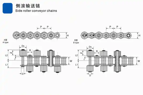
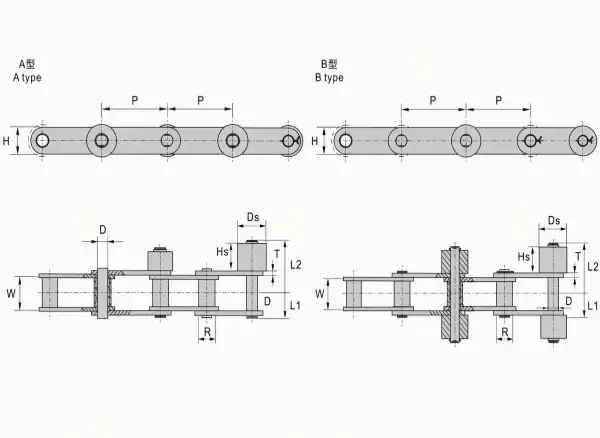
The supplied technical drawings show two configurations:
The technical tables provide chain pitch, roller diameter, inner plate width, pin diameter, plate thickness, inner plate depth, pin length, side roller dimensions, and weight per meter.
The numerical specifications below are transcribed from the supplied A and B images. Final production should be based on the approved technical drawing and confirmed chain specification.
The side roller conveyor chain consists of:
The technical drawings include the following dimensions:
The side roller arrangement is designed for conveyor systems in which products are supported, transferred, accumulated, or moved along a guided conveyor path.
The A Type configuration is shown in both supplied technical drawings. Its data table lists chain numbers 40, 50, 60, 80, and 100.
The B Type configuration is also shown in both drawings. In the A image, the chain number is listed alongside the corresponding A Type number. In the B image, the table provides paired models such as:
The exact dimensions should be selected according to the chain type, side roller arrangement, guide rail, sprocket, and conveyor layout.
The A image table includes chain numbers 40, 50, 60, 80, and 100 for both A Type and B Type.
Note: The pitch values in the source table are shown with three decimal places. The Excel file preserves the corresponding precision for the pitch column.
The B image table lists paired A Type and B Type chain numbers. Shared parameters are presented as grouped values across each model pair in the original layout.
Note: The B image does not display a plastic-roller weight for C2082 or C2102. These cells are marked as
—rather than filled with an estimated value.
Side rollers can allow discrete products to stop or idle while the chain continues to move. This configuration is commonly associated with accumulating conveyor sections.
The drawings show two different side roller chain configurations, allowing the chain layout to be selected according to the conveyor structure and product-transfer requirements.
The tables provide separate steel-roller and plastic-roller weight references. This allows the conveyor designer to compare the two configurations during equipment planning.
The supplied specifications cover:
Side roller chains can be considered for equipment requiring:
Public technical references describe side rollers and top rollers as useful for allowing discrete products to idle while the conveyor chain continues to run. This makes side roller chains relevant to accumulation conveyor sections.
Potential applications include:
The public references also identify conveyor chains as suitable for transporting unit loads and bulk goods, with specialized chain designs and attachments available for different conveyor layouts.
Applications should be evaluated according to the conveyed product, operating environment, conveyor speed, guide rail structure, sprocket arrangement, maintenance requirements, and required roller configuration.
OEM and ODM services can be arranged according to:
Samples can be supplied for checking:
The A image has been:
Side Roller Conveyor Chain Manufacturer
The B image has been:
auto parts, construction machinery spare parts and motorcycle parts ,including engine parts ,chassis parts ,braking systems parts,
electrical parts,gearbox parts,hydraulic parts,filter system parts.
 English
 Russian