| VEHICLE FITMENT | |
| TYPE | Heavy-duty cranked-link transmission chain |
| OE NUMBER | |
| MATERIAL |
| VEHICLE FITMENT | |
| TYPE | Heavy-duty cranked-link transmission chain |
| OE NUMBER | |
| MATERIAL | |
| SIZE | Standard size or ODM size |
| CUSTOMIZED | YES |
| CONDITION | Brand new |
| MOQ | |
| PACKAGE | Standard or as customer requirements |
Heavy-duty cranked-link transmission chains are offset-sidebar transmission chains designed for demanding mechanical drive applications. Their cranked-link plate geometry allows the chain to form a robust roller-and-pin assembly while providing the dimensional structure required for heavy-duty power transmission.
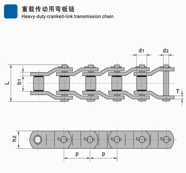
The supplied technical drawing shows two views of the chain:
The supplied parameter table lists 13 chain numbers across standard and special-size series, including 2010, 2512, 2814, 3315, 3618, 4020, 4824, WG781, WG103, WG140, WG9525, WB7900, and WB7938.
All exact numerical values in this page are transcribed from the supplied technical image. Public sources are used only for general standard and application background.
The offset or cranked-link plate form is designed for heavy-duty chain-drive construction. The upper drawing shows the characteristic stepped plate profile around the rollers and pins.
The table includes large pitch options from 63.50 mm to 152.40 mm, together with corresponding roller, pin, plate, tensile-strength, and weight values. These dimensions are intended for equipment matching and engineering review.
The technical drawing identifies the main roller and pin dimensions, including d1, d2, b1, L, and T. These dimensions should be checked against the sprocket, shaft, chain guide, and existing chain assembly.
The supplied table covers 13 chain numbers. This allows users to compare the required pitch, roller diameter, pin diameter, chain width, tensile-strength field, and weight per meter for different transmission requirements.
Cranked-link transmission chains are typically considered for heavy-duty mechanical drives and engineered chain systems where high load capacity, dimensional matching, and reliable sprocket engagement are important.
Final selection must be based on the complete drive calculation, operating conditions, sprocket design, safety factor, lubrication, and maintenance requirements.
The U.T.S values are minimum ultimate tensile-strength specifications shown in the source table. They are not allowable working-load values. Working load must be calculated separately using the full drive design and an appropriate safety factor.
The supplied technical drawing has been horizontally corrected and redrawn as a separate engineering image. It retains:
重载传动用弯板链Heavy-duty cranked-link transmission chainHeavy-Duty Cranked-Link Transmission Chain | Industrial Chain
The numeric chain series in the supplied table cover pitches from 63.50 mm to 152.40 mm. The listed U.T.S values range from 262.00 kN for 2010 to 1,521.00 kN for 4824.
These values should be used for comparison against the required chain size and drive arrangement, not as a substitute for a complete transmission calculation.
The listed WG models are:
The WG series in the supplied table covers pitch values from 78.18 mm to 140.00 mm and U.T.S values from 313.60 kN to 1,176.00 kN.
The listed WB models are:
The table identifies pitch values of 79.00 mm and 79.38 mm, with U.T.S values of 381.00 kN and 509.00 kN, respectively.
Heavy-duty cranked-link transmission chains are generally considered for engineered power-transmission systems and industrial machinery where a larger chain size and offset-sidebar construction are required.
Typical application areas may include:
Some public industry materials also describe cranked-link or related heavy-duty engineering chains for conveyors, stackers, sorters, trimmer saws, and other industrial equipment. The exact suitability of any chain number must be verified against the equipment design.
Technical matching can be based on:
For replacement applications, provide a chain sample or clear dimensional drawings. Pitch alone is not sufficient to confirm interchangeability.
Material grade, heat treatment, surface treatment, coating, corrosion resistance, fatigue life, wear life, and working-load rating are not specified in the supplied image. These details should be confirmed separately before being included in a final purchase specification.
auto parts, construction machinery spare parts and motorcycle parts ,including engine parts ,chassis parts ,braking systems parts,
electrical parts,gearbox parts,hydraulic parts,filter system parts.
 English
 Russian