| VEHICLE FITMENT | |
| TYPE | Perpendicular Elevator Chains |
| OE NUMBER | |
| MATERIAL | Metal |
| VEHICLE FITMENT | |
| TYPE | Perpendicular Elevator Chains |
| OE NUMBER | |
| MATERIAL | Metal |
| SIZE | Standard size or ODM size |
| CUSTOMIZED | Yes |
| CONDITION | Brand new |
| MOQ | |
| PACKAGE |
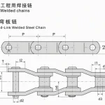
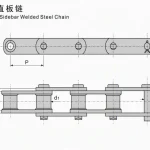
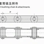
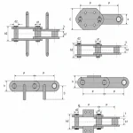
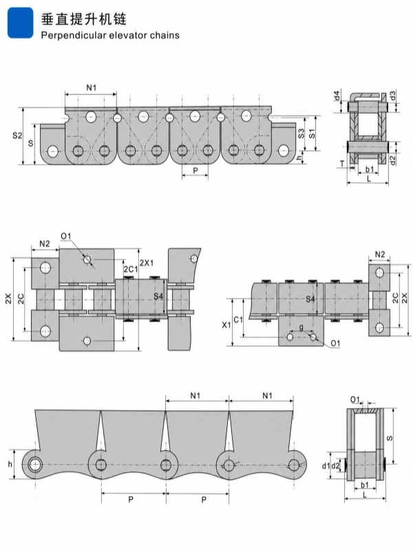
Perpendicular elevator chains are engineered chains designed for vertical lifting and bucket-elevator systems. The supplied technical drawing shows multiple chain and attachment configurations, including chain plates, rollers, pins, projecting attachments, bucket or attachment plates, and section views for matching the elevator assembly.
The supplied parameter table includes five models:
The drawing and table include references for pitch, inner plate width, roller diameter, chain height, plate thickness, attachment spacing, pin length, section dimensions, minimum ultimate tensile strength, and weight per meter.
The drawing shows chain arrangements designed for vertical elevator equipment. The chain assembly includes repeating chain plates, rollers, pins, attachment plates, and projecting components for connecting buckets or elevator attachments.
The technical drawing presents several views of attachment arrangements, including:
The correct attachment arrangement should be matched to the bucket layout, elevator frame, chain-wheel geometry, and equipment drawing.
The supplied drawing includes the following visible fields:
Blank values are preserved where the supplied source image shows no value. No missing attachment dimensions have been inferred.
Perpendicular Elevator Chains | Cement and Bulk Material Elevator Chain
These models use a pitch of 19.05 mm and share the main chain dimensions shown in the source table. Their attachment-related fields differ in the source data, so the correct model should be matched to the original elevator attachment arrangement.
These models use a pitch of 25.4 mm. The source table shows different attachment data for the two model forms, including a supplied g value for 16A-LK2 and a blank source field for 16A-LK1.
The 216A-LU model uses a pitch of 50.8 mm. Several attachment fields are blank in the source table and are intentionally retained as blank. Confirm the attachment geometry against the original equipment drawing before ordering.
Public engineering references describe bucket and vertical elevator chains in applications such as:
Bucket elevators convey bulk materials vertically along a production line. Chain-based systems are commonly considered where the conveyed material, temperature, particle size, density, or shock conditions require an engineered chain configuration.
Select the model based on:
The supplied pitch values are:
Pitch must match the chain-wheel tooth spacing and the complete elevator chain path.
Check the complete attachment geometry, including:
Do not assume that two models with the same pitch have interchangeable attachments.
Provide:
The source table includes Ultimate Tensile Strength Min and Weight per Meter. These values should not be treated as an automatic allowable working-load rating. Final selection requires a complete engineering calculation using the actual chain tension, bucket weight, material load, speed, shock factor, fatigue considerations, and safety factor.
Public industry sources identify temperature, particle size, density, abrasion, and shock loading as important factors in bucket-elevator selection. Chain bucket elevators are often considered for hot, abrasive, coarse, or dense bulk material, but the correct equipment and chain type must be confirmed by the system designer.
For cement and building-material applications, provide:
Custom review can be based on:
auto parts, construction machinery spare parts and motorcycle parts ,including engine parts ,chassis parts ,braking systems parts,
electrical parts,gearbox parts,hydraulic parts,filter system parts.
 English
 Russian