| VEHICLE FITMENT | |
| TYPE | straight sidebar welded steel chain |
| OE NUMBER | |
| MATERIAL | Metal |
| VEHICLE FITMENT | |
| TYPE | straight sidebar welded steel chain |
| OE NUMBER | |
| MATERIAL | Metal |
| SIZE | Standard size or ODM size |
| CUSTOMIZED | Yes |
| CONDITION | Brand new |
| MOQ | |
| PACKAGE | Standard or as customer requirements |
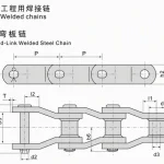
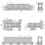
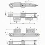
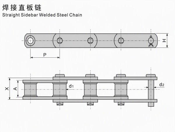
Straight sidebar welded steel chain is an engineered welded chain designed for demanding conveying and material-handling systems. The straight-sidebar profile shown in the supplied technical drawing provides a regular chain path with welded sidebars, rollers, pins, and bush/roller components for industrial equipment integration.
The supplied drawing includes:
The supplied table includes four chain models:
All exact dimensions and numerical values in this page are transcribed from the supplied image. Public references are used only for general application and selection background.
The straight-sidebar construction provides a continuous side-plate profile for chain routing and equipment integration. The drawing shows a regular upper plan view and a lower assembly view with rollers, pins, sidebars, and centerlines.
The welded chain format is intended for engineered conveying systems where the chain must work with sprockets, guides, shafts, product supports, or other machine components. The exact construction and service configuration must be confirmed against the equipment drawing.
The supplied table covers four models with pitches from 66.27 mm to 153.67 mm:
The table lists:
Straight Sidebar Welded Steel Chain
U.T.S. and A.T.S. are source table fields. They should not be treated as a complete working-load calculation without checking safety factor, chain speed, shock loading, fatigue, sprocket selection, lubrication, and the actual machine design.
Straight sidebar welded steel chains are generally considered for heavy-duty conveying and industrial material-handling applications such as:
Public industry references describe welded steel chains as suitable for demanding forestry, mill, bulk-handling, and conveyor environments. Actual suitability of a specific WRC model must be confirmed against the equipment load, chain speed, shock conditions, environment, and maintenance plan.
The supplied models use the following pitches:
Pitch must match the sprocket or wheel tooth spacing and the complete conveyor layout.
Confirm:
These dimensions affect sprocket engagement, guide clearance, chain alignment, and equipment integration.
Provide the following information before final selection:
The source table includes U.T.S. and A.T.S. values. These fields should be reviewed with the complete drive calculation rather than used as a standalone working-load guarantee.
The straight-sidebar form provides a consistent outer profile for chain guides and equipment layout. Confirm the side clearance and sprocket width against the selected model.
The chain is presented as an engineered welded steel chain for industrial conveyor and bulk-handling systems. The final chain construction, treatment, attachment details, and service rating must be confirmed in the purchase specification.
The WRC-78 through WRC-132 models provide multiple pitch options for equipment with different chain spacing and load requirements.
For replacement applications, pitch alone is not sufficient. Send the existing chain sample, sprocket or wheel drawing, pin and roller measurements, and operating conditions for technical matching.
Custom engineering review can be based on:
Material grade, heat treatment, surface treatment, coating, corrosion resistance, wear life, service life, working-load rating, and certification are not specified in the supplied image. Confirm these items separately before adding them to a purchase specification.
Request a Quote for Straight Sidebar Welded Steel Chain
Please provide:
auto parts, construction machinery spare parts and motorcycle parts ,including engine parts ,chassis parts ,braking systems parts,
electrical parts,gearbox parts,hydraulic parts,filter system parts.
 English
 Russian