| VEHICLE FITMENT | |
| TYPE | Engineering welded chains |
| OE NUMBER | |
| MATERIAL |
| VEHICLE FITMENT | |
| TYPE | Engineering welded chains |
| OE NUMBER | |
| MATERIAL | |
| SIZE | Standard size or ODM size |
| CUSTOMIZED | |
| CONDITION | Brand new |
| MOQ | |
| PACKAGE | Standard or as customer requirements |
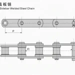
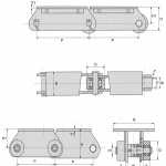
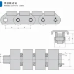
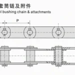
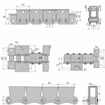
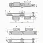
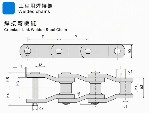
Engineering welded chains are engineered chains for demanding conveyor, elevator, and bulk-material handling systems. The supplied technical drawing shows a Cranked-Link Welded Steel Chain with welded crank sidebars, rollers, pins, chain plates, and dimensional references for chain pitch and side-clearance design.
The supplied page includes two specification tables:
The supplied models are:
All exact numerical values in this product page are transcribed from the supplied image. Public sources are used only for general engineering-chain applications and selection background.
The source drawing prints the English heading as “Cramked-Link Welded Steel Chain.” The phrase is preserved in the technical drawing image. The product-page title uses the conventional spelling “Cranked-Link Welded Steel Chain.”
The drawing shows a welded crank-link profile with repeating upper and lower sidebars connected around rollers and pins. This arrangement is designed for integration into engineered conveying equipment and chain-driven material-handling systems.
The technical drawing includes visible references for:
The supplied tables cover seven chain models with pitch values from 66.27 mm to 153.67 mm. This range supports different equipment layouts, sprocket sizes, chain widths, and load requirements.
The first table provides the main chain dimensions. The second table provides additional sidebar dimensions, plate thickness, U.T.S., and A.T.S. Keeping the two tables separate follows the original source layout and helps match the drawing to a technical purchase specification.
Pitch is the chain pitch shown in the source table.d1 max, d2 max, and d3 min are diameter-related fields shown in the source.b1 min and h2 are chain/plate dimensional fields shown in the source.l1 min and l2 min are minimum link or sidebar reference dimensions.mm.b2 max, b3 min, b4 max, b5 max, and b6 max are additional sidebar and assembly dimensions shown in the source table.T is the plate-thickness field shown in the source table.U.T.S. and A.T.S. are the strength fields shown in the source table.mm; U.T.S. and A.T.S. are in kN.U.T.S. and A.T.S. are source-table fields. They should not be treated as an automatic allowable working-load rating. Final selection requires a complete engineering calculation with safety factor, speed, shock loading, fatigue, sprocket design, lubrication, and operating environment.
Engineering Welded Chain | W78 to W132 Cranked-Link Chain
Public engineering-chain references describe welded steel and cranked-link chains in applications such as:
Welded chains are typically considered where the conveyor or drive system requires an engineered chain arrangement for demanding handling conditions. The suitable chain model depends on the conveyed material, chain speed, pitch, sprocket design, impact level, environmental contamination, lubrication, and maintenance access.
Custom review can be based on:
Material grade, heat treatment, surface treatment, coating, corrosion resistance, wear life, service life, certification, and allowable working-load rating are not specified in the supplied image. Confirm these items separately before adding them to a purchase specification.
auto parts, construction machinery spare parts and motorcycle parts ,including engine parts ,chassis parts ,braking systems parts,
electrical parts,gearbox parts,hydraulic parts,filter system parts.
 English
 Russian