| VEHICLE FITMENT | |
| TYPE | Engineering steel bushing chain |
| OE NUMBER | |
| MATERIAL |
| VEHICLE FITMENT | |
| TYPE | Engineering steel bushing chain |
| OE NUMBER | |
| MATERIAL | |
| SIZE | Standard size or ODM size |
| CUSTOMIZED | Yes |
| CONDITION | Brand new |
| MOQ | |
| PACKAGE | Standard or as customer requirements |
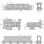
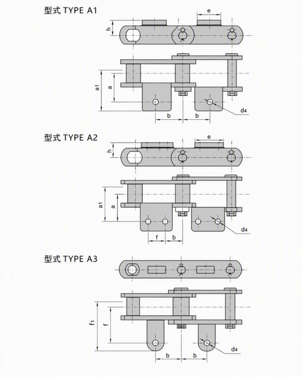
Engineering steel bushing chains are heavy-duty engineered chains designed for industrial conveying, mechanical handling, and custom chain assemblies. The supplied drawings show the base engineering steel bushing chain together with three attachment configurations: TYPE A1, TYPE A2, and TYPE A3.
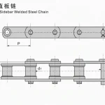
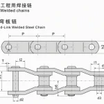
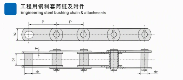
The first technical drawing shows the main chain construction, including chain plates, bushes, pins, rollers, centerlines, pitch, and key dimensional references. The second drawing shows three attachment layouts with different plate positions and hole arrangements.
The supplied main-chain table includes six chain numbers:
The attachment table includes the compatible chain numbers and dimensions for TYPE A1, TYPE A2, and TYPE A3.
All exact numerical values in this page are transcribed from the supplied technical images. Public references are used only for general engineering-chain application and selection background.
The main drawing shows a bushing-chain assembly with chain plates, bushes, pins, rollers, and connecting components. The chain dimensions are intended to support equipment matching, replacement evaluation, and engineered conveyor design.
The second drawing identifies three attachment types:
The attachment type must be selected according to the machine drawing, conveyed material, mounting direction, guide arrangement, and required hole position.
The main table provides:
A1, A2, and A3 attachments provide different mounting surfaces and hole configurations. The attachment geometry should be checked against the conveyor frame, flights, product supports, guide rails, sprockets, and adjacent machine components.
Engineering bushing chains and their attachments are generally considered for industrial conveyors, bucket elevators, transfer systems, tension linkages, and other engineered handling equipment. Final selection depends on the complete chain drive calculation and operating conditions.
The source image provides the field labels and values. U.T.S. and A.T.S. should not be treated as a complete working-load calculation without checking the drive design, safety factor, speed, shock load, lubrication, and operating environment.
Engineering Steel Bushing Chain and Attachments
Engineering Steel Bushing Chain and Attachments 2
The A1 drawing shows attachment plates positioned below the chain with a pair of mounting holes on each attachment plate. The visible dimensions include a, a1, b, d4, e, and h.
The A2 drawing shows a different attachment-hole arrangement from A1, including the visible f, b, and d4 dimensions. Confirm the plate position and hole spacing before integrating the chain into the conveyor assembly.
The A3 drawing shows an attachment layout with the dimensions f, b, c, f1, and d4. Only the S188 row is shown in the supplied A3 table.
Engineering steel bushing chains with attachments are generally considered for industrial handling and engineered chain assemblies such as:
The exact application of S102B, S110, S111, S131, S150, or S188 should be confirmed against the equipment drawing, chain drive, sprocket or wheel arrangement, attachment load, speed, and service environment.
Engineering steel bushing chains can be reviewed for custom attachment requirements based on:
Material grade, heat treatment, surface treatment, coating, corrosion resistance, wear life, service life, and working-load rating are not specified in the supplied images. Confirm these details separately before adding them to a purchase specification.
Request a Quote for Engineering Steel Bushing Chain and Attachments
Please provide:
auto parts, construction machinery spare parts and motorcycle parts ,including engine parts ,chassis parts ,braking systems parts,
electrical parts,gearbox parts,hydraulic parts,filter system parts.
 English
 Russian